Tuesday, April 16, 2024

Northrop Grumman's Future Strike Aircraft (FSA) bomber projects

After the end of the Cold War and the fall of the Soviet Union, a number of studies concluded that in light of the exorbitant unit cost of the Northrop Grumman B-2 Spirit flying wing bomber, the need for the US Air Force to acquire more B-2s after the first twenty-one aircraft out of the 132 B-2s originally planned to be procured was not worth it. However, in 1998, a congressional panel, known as the Panel to Review Long Range Airpower, took a serious look at the merits of resuming production of the B-2 because some supporters of the B-2 were of the opinion that acquiring twenty more B-2s would be a cost-saving measure on the grounds that the B-2 itself would be able to deeply penetrate anti-aircraft defenses and use low-cost, short-range attack weapons rather than expensive standoff weapons. In the end, the congressional panel opted to re-allocate funds for B-2 upgrades or developing technology for a future strategic bomber. A roadmap issued by the US Air Force in March 1999 regarding the future of the US bomber fleet called for a new bomber to be fielded by 2037 (although some in Congress wanted a long-term B-52H and B-1B replacement to enter service before 2037).

Although the March 1999 roadmap by the Air Force for the long-term future of its bomber fleet was criticized on the grounds that the B-52H, B-1B, and B-2 fleets would eventually become obsolete and overstretched, in early June 1999 the USAF's Air Force Aeronautical Systems Center commenced the Future Strike Aircraft (FSA) program awarding year-long study contracts to Boeing, Lockheed Martin, and Northrop Grumman for those companies to investigate designs for a future global strike bomber to be operational by 2030. By September, Northrop Grumman unveiled a series of FSA designs for a new global strike bomber to replace the B-2, and these concepts were grouped into subsonic, supersonic, and hypersonic classes, and speed was emphasized by Northrop Grumman as the key trade-off.

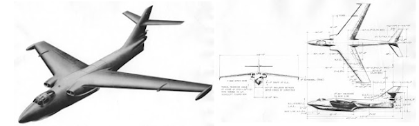
Left: Three-view of the Northrop Grumman Mach 2 FSA concept
Right: Computer-generated image of the Northrop Grumman Mach 4 FSA design

The subsonic FSA design by Northrop Grumman took the form of a strategic flying wing bomber with a number of refinements to the design of the B-2, although additional published details of this proposal are sorely lacking. Northrop Grumman proposed two FSA designs capable of cruising at speeds within the supersonic flight regime, both resembling a cross between the B-1B and B-2. One was a blended wing body delta-shaped aircraft with small cranked wing extensions, a W-shaped trailing edge of the wings, and outward canted vertical stabilizers, which measured 143 feet (43.58 meters) long and had a wingspan of 118 feet (36 meters). It was powered by two supercruise turbofan engines (unspecified, but probably derived from the Pratt & Whitney F119), which could allow for cruising at speeds of Mach 2 without an afterburner. The other supersonic FSA proposal from Northrop Grumman had a top speed of Mach 4 and inward canted vertical stabilizers, and it was powered by four jet engines housed in two paired nacelles outboard of the vertical stabilizers, functioning as turbofans for low supersonic speeds and operating as turboramjets at speeds of Mach 4. Like the subsonic flying proposal, both Northrop Grumman supersonic FSA designs were stealthy and carried a crew of two, with the weapons load for these aircraft comprised laser-guided bombs, gravity bombs, and cruise missiles carried inside internal weapons bays. Northrop Grumman also envisaged an unmanned version of its subsonic flying wing concept, the Unmanned Global Strike Aircraft, which either could operate autonomously or within a formation of up to four aircraft controlled by a third crewmember in a modified B-2.    

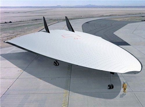
A computer-generated image of the Northrop Grumman hypersonic bomber design on the tarmac 

Northrop Grumman's hypersonic bomber proposal was arguably the most cutting-edge FSA design to be worked out by the company for the FSA program. It was a futuristic-looking bomber with blunt wings, twin vertical stabilizers, and a nose with a round curvature, and it featured a space capsule-type window, which meant that the pilot had to rely on a visually-aided cockpit requiring sensors even for takeoff and landing. Power was provided by scramjet engines at the rear of the aircraft, and to reach hypersonic speeds, the hypersonic FSA design had to rely on jet- or rocket-assisted climb to very high altitudes, with the scramjet igniting as the engine turbines were sealed off from the incoming air. In order to scout enemy targets over distances of 125 miles (201 km) or more, the hypersonic bomber was equipped with multispectral sensors and a high energy laser with a range of frequencies, and offensive weapons were launched from multiple rails from the rear of the aircraft's vertical tails at hypersonic speeds. Given the astronomically high temperatures associated with hypersonic flight, the Northrop Grumman hypersonic bomber would have been constructed from heat-resistant materials, namely carbon-carbon, Beta-21S aluminum, and lightweight ceramics.

Additional data on Northrop Grumman's bomber designs for the Future Strike Aircraft program can be found at these links:

Monday, April 15, 2024

Unbuilt McDonnell Douglas jumbo jets, part 2: the MD-12

In the early 1990s, the Long Beach division of McDonnell Douglas was quite busy with manufacture of the DC-9 derived MD-80 and MD-90 short-haul narrow-body airliners and the MD-11 derivative of the DC-10 trijet widebody airliner, leaving it with a narrower portfolio of in-production airliners than the Boeing company. However, McDonnell Douglas was not standing still when in came to development of widebody airliners, and while it is well known that the Boeing 717 airliner began life as the youngest son of the DC-9, the MD-95, a growing future market demand for a large airliner to handle increased air traffic in the Asia-Pacific realm would give McDonnell Douglas an unlikely impetus to take a second jab at development of a very large airliner.

An artist's concept of the McDonnell Douglas MD-12 trijet, the first airliner to bear the MD-12 designation

With sales of the MD-11 to the airlines coming off to a slow start, in October 1990 McDonnell Douglas proposed a stretched derivative of the MD-11 under the designation MD-12X (the MD-12 designation was first applied to an initial stretched MD-11 proposal with fly-by-wire controls conceived in 1987). The MD-12X was 237 feet 11 in (72.5 meters) long with a wingspan of 212 feet 6 in (64.8 meters), and lacking the MD-11's winglets, it had a seating capacity for 375 passengers in three-class configuration and a range of 10,357 miles (16,668 km). McDonnell Douglas began pitching the MD-12X concept to the airlines in October 1991, and the following month it signed a Memorandum of Understanding with the Taiwan Aerospace Corporation  to form a joint venture to build the MD-12X, with McDD being the majority shareholder (51%) and Taiwan Aerospace (40%) and other Asian companies (9%) having the remaining shares. To help attract foreign investment in the MD-12X project, McDonnell Douglas split its commercial aviation business from the military aviation branch which built the C-17 Globemaster III airlifter.

Company artwork of the McDonnell Douglas MD-12 twin-deck airliner. The similarity to the A380 is quite undeniable.

Although several airlines took an interest in the MD-12X proposal, they increasingly desired a more fuel-efficient four-engine high-capacity airliner with greater growth potential. In response, McDonnell Douglas in April 1992 unveiled the MD-12 four-engine airliner design, which was similar in concept to the Airbus A3XX (later A380) and the Boeing New Large Airplane (NLA) designs. Like the D-916C, D-918, D-950, D-952, and D-956 designs conceived in the mid-1960s, the MD-12 was a twin-deck airliner with turbofans, measuring 208 feet (63.40 meters) in length with a wingspan of 213 feet (64.92 meters), a height of 74 feet (22.55 meters), a wing area of 5,846 ft2 (543.1 m2), a gross takeoff weight of 949,000 lb (430,500 kg), and a speed of 650 mph (1,050 km/h). Four baseline MD-12 variants were offered, the 430-seat MD-12 Long Range design with a range of 9,229 miles (14,853 km), the 511-seat MD-12 High Capacity design with a range of 8,251 miles (13,279 km), the 430-seat MD-12 Combi passenger/cargo variant with a range of 7,169 miles (11,537 km), and the MD-12 Freighter with a cargo capacity of 274,600 lb (124,556 kg). The 689-seat MD-12 Stretch was to be 26 feet 6 in (8 meters) than the baseline MD-12 with a wingspan of 229 feet (69.8 meters), and two subvariants were offered, the MD-12 Stretch MR (Medium Range) with a range of 5,800 miles (9,334 km) and the MD-12 Stretch LR (Long Range) with a range of 7,800 miles (12,553 km). The 430-seat MD-12 Twin had the same length as the basic MD-12 but had the same wingspan as the MD-12 Stretch, two turbofan engines, and a range of 5,000 miles (8,046 km). Engine options for the baseline MD-12 and MD-12 Stretch MR included the 61,500 lb (274 kN) thrust General Electric CF6, four 62,000 lb (28,122 kg) thrust Pratt & Whitney PW4400, and the 64,000 lb (29,029 kg) thrust Rolls-Royce Trent 764, while turbofans with 90,000 lb (400 kN) thrust were planned for the MD-12 Stretch LR and MD-12 Twin. Like the MD-11, the MD-12 had crew of two and a glass cockpit, and it sported winglets similar to those developed for the A380. With a fuselage measuring 24 feet 3 in (7.4 meters) wide and 27 feet 11 in (8.5 meters) high, it would have been the most spacious airliner with either a two- or three-aisle cabin. The MD-12 would offer passengers the roomiest and most comfortable cabins in the sky, and the passenger decks featured the latest in passenger amenities with options including an office in the sky, exercise room, in-seat video, and seat telephones.

Given expected high development costs of the MD-12, the planned joint venture between McDonnell Douglas' commercial aircraft business and Taiwan Aerospace would combine the McDonnell Douglas resources located in the United States and Taiwan. Significant parts fabrication and major sub-assembly work was to be undertaken in Taiwan, and the final assembly of the MD-12 would take place at a new site in the United States (Belleville, Fort Worth, Houston, Kansas City, Mesa, Mobile, Salt Lake City, Shreveport, and Tulsa were accepted as candidates for an MD-12 final assembly facility). Plans called for the MD-12 to make its first flight in 1995 and enter service in 1997, but the MD-12 project was all for naught. No airline orders were placed for the MD-12 despite an aggressive marketing campaign by McDonnell Douglas, and when Taiwan Aerospace decided to quit participation in the MD-12 program, a financially cash-strapped McDonnell Douglas, lacking any other equity partners to keep the MD-12 alive, instantly shelved the MD-12 project.

References:

Norris, G., and Wagner, M., 2005. Airbus A380: Superjumbo of the 21st Century. St. Paul, MN: Zenith Press.

Steffen, A., 2002. McDonnell Douglas MD-11: A Long Beach Swansong. Hinckley, UK: Midland Publishing.

Sunday, April 14, 2024

Unbuilt McDonnell Douglas jumbo jets, part 1: the D-916C, D-918, D-950, D-952, and D-956

Today, there are two gigantic passenger/freight aircraft flying in our skies, the Boeing 747 first flown in 1969 and the larger double-deck Airbus A380 built early in this century, and these airliners have come to be colloquially known as the "jumbo jets" (the A380 is more popularly nicknamed "superjumbo" given its larger wingspan and greater seating capacity). However, what many people don't know is that once upon a time, in the late 1960s and again in the early 1990s, Douglas and later McDonnell Douglas worked out design studies for jumbo jets similar to or rivaling the Boeing 747 in size, seating capacity, and wingspan. Since Douglas tinkered with very large airliner proposals in the mid-1960s before it merged with McDonnell in 1967 to form McDonnell Douglas, and the aerospace industry in Long Beach returned to double-deck airliner design in the early 1990s, I'm covering the history of jumbo jet design in Long Beach in two parts, with this blog post dedicated to proposals for a 747- and A380-type airliner envisaged by Douglas in the 1960s. 

Artwork of the Douglas D-918 double-deck airliner, which was derived from the losing D-916 submission for the CX-HLS competition. 

In early 1965, Douglas began tinkering with design studies for an airliner comparable to the Boeing 747 when it proposed a commercial derivative of the losing D-916 strategic airlifter design for the CX-HLS (Cargo Experimental - Heavy Logistics System) competition, known as D-916C by the company. Like the D-916, the D-916C had shoulder-mounted wings and the cockpit situated at the top in a flight deck that formed a hump similar to that of the 747. The airliner variant of the D-916C had a seating capacity for 616 passengers, with 219 seated on the first deck, 300 passengers seated in a full upper deck, and 96 people (36 seats in a private compartment and 60 seats in the siesta balcony) seated in the partial upper deck at the level of the cockpit, and its lower deck could also carry 16,000 cubic feet (453 cubic meters) of cargo. When configured as a commercial freighter, the D-916C could carry 30,720 cubic feet (870 cubic meters) of freight within the two full decks. Douglas simultaneously conceived another similarly-sized twin-deck airliner project with shoulder-mounted wings, the D-918, which had a seating capacity for 900 passengers on two full decks and a partial upper deck at the level of the cockpit.

Left: Three-view drawing of the Douglas D-950-30
Right: Three-view drawing of the Douglas D-952-30

In the second half of 1965 the D-916C and D-918 projects faded away as Douglas envisaged a pair of twin-deck four-engine airliner projects, internally called D-950 and D-952, which were powered by four 40,000 lb (177.9 kN) thrust General Electric CF6 or Pratt & Whitney JTF-14E turbofans. Both airliner proposals retained the double-bubble cross-section of the D-916C and D-918, and the D-950 had a wingspan of 167 feet 6 in (51.04 meters) and a range of 6,000 miles (9,656 km), while the D-952 was to have a wingspan of 206 feet 9 in (63 meters). Three iterations of the D-950 were considered, the 376-seat D-950-10 with a length of 180 feet 4 in (55 meters), the 457-seat D-950-30 with a length of 194 feet 4 in (58 metes), and the 524-seat D-950-50 having a fuselage 206 feet 4 in (62.89 meters) long, and they had a maximum takeoff weight of 275,000 lb (124,738 lb). As a freighter, the D-950 was to carry two side-by-side 88 x 125 inch pallets on the main deck, and single pallets on the upper deck. The D-952 had a more voluminous cross-section of both decks, which had higher cabin ceilings, and two variants of the D-952 were studied, the 458-seat D-952-10 with a length of 182 feet (55.47 meters) and a range of 4,000 miles (6,437 kg), and the 563-seat D-952-30 measuring 212 feet (64.61 meters) long and having an operating range of either 3,500 miles (5,632 km) with a 150,000 lb (68,039 kg) payload or 2,150 miles (3,460 kg) when carrying a 300,000 lb (136,077 kg) payload. Work on the D-950 project was shelved by the time that the Boeing 747 program was launched after Pan Am ordered for 25 aircraft on April 13, 1966, but Douglas continued development of the D-952 on a low-key basis, tentatively eyeing a first flight of 1972 and service entry in 1975 for the D-952, eventually abandoning all work on the D-952 after market researchers concluded that a very large jet airliner was not yet viable given that the Boeing 707 and Douglas DC-8 could occupy most of long-haul routes for which the D-952 had been designed. 

Artwork of the Douglas D-956-13 double-deck airliner project in flight with the writing "Douglas DC-10" on the fuselage. 

Even before the D-950 and D-952 were axed, Douglas worked out one more project in late 1965 for a double-deck airliner/commercial freighter, designated D-956, steadfast in its opinion that airfreight growth was central to the future of large transport aircraft. Like the D-950 and D-952, the D-956 had low-mounted wings but differed in having a wider fuselage and a wingspan of 191 feet (58.21 meters), and three different fuselage lengths were investigated for this aircraft along with two engine options, the General Electric TF39 and Pratt & Whitney JT9D turbofans, which generated 41,000 lb (182.38 kN) of thrust. The baseline TF39-powered D-956-13 and JT9D-powered D-956-23 airliner proposals along with the baseline D-956-13F and D-956-23F freighter designs were 180 feet (54.86 meters) long, and the D-956-13 and -15 could carry 400 passengers over a distance of 6,000 miles (10,460 km), while the D-956-13F and -15F were to haul 215,000 lb (97,522 kg) of freight over a range of 2,775 miles (4,466 km) or 200,000 lb (90,718 kg) of freight in a typical transatlantic flight over a distance of 3,500 miles (5,632 km). Four stretched D-956 proposals were conceived, the TF39-powered D-956-14 and JT9D-powered D-956-24 with a length of 200 feet (61 meters), a seating capacity for 500 passengers, and a range of 5,100 miles (8,208 km), and the even bigger 602-seat D-956-15 (with TF39s) and D-956-25 (with JT9Ds) with a length of 220 feet (67 meters) and an operating range of 3,500 miles (5,632 km). One D-956 design study was proposed with a length of 260 feet (79 meters) and a single deck fuselage accommodating 585 passengers, but was quickly shelved because it had less fuel efficiency than the double-deck D-956 designs. The D-956-15 and -25 iterations were selected for further development because Douglas considered the seat-mile operating costs of those designs to be 30 percent cheaper than that of the DC-8-61. However, the D-956 did not proceed beyond the design phase because Douglas in May 1966 turned its attention to design of a twin-engine successor to the Boeing 727 in response to an American Airlines requirement issued in April for a twin-engine airliner with 250 seats and capable of operating from 7,000 foot (2,134 meter) runways.

References:

Endres, Gunter, 1998. McDonnell Douglas DC-10. St. Paul, MN: MBI Publishing. 

Waddington, T., 2000. McDonnell Douglas DC-10. Miami, FL: World Transport Press. 

Tuesday, April 9, 2024

San Diego's long-range maritime patrol jet seaplane designs for the Navy

The invention of the jet engine undoubtedly had a profound impact on the performance of a brand new generation of American bomber aircraft coming of age after World War II by offering increased speed at higher altitudes occupied by the piston-powered B-29, B-36, and B-50. Although the exclusive focus of the US Navy's efforts to make the gradual transition to jet aircraft in 1945 involved deploying its first jet fighters, the Martin P4M Mercator land-based patrol aircraft flown in 1946 had a unusual combo of both piston and jet engines like the Ryan FR Fireball fighter, with two auxiliary turbojet engines at the rear of the piston engine nacelles, and archival documents demonstrate that the aerospace industry in San Diego explored the idea of a jet-powered seaplane even before the end of World War II. This blog post will give an overview of Convair's jet-powered patrol flying boat designs for the US Navy that never were, including an early jet patrol flying boat design by Convair and a giant seaplane running on nuclear power.

An artist's rendering of the Convair High Speed Flying Boat project from May 1945

Convair began investigating the benefits of jet propulsion for a patrol aircraft in December 1944 when it analyzed three different design approaches to a maritime patrol seaplane design powered by two Pratt & Whitney R-4360 Wasp Major radial piston engines and two auxiliary General Electric J35 (TG-180) turbojets. One design involved a patrol flying boat similar in hull design to the XP5Y and R3Y which had two R-4360s and two J35s situated at the rear of the engine nacelles housing the Wasp Majors, and which had a gross weight of 85,000 lb (38,555 kg). A second design approach featured a twin-float seaplane which had the same gross weight as the flying boat design but had a slender fuselage and the J35s below the engine nacelles for the R-4360s, and two iterations of this design configuration were proposed, only differing in size and wing loading. The third design approach involved an unorthodox single-float seaplane whose tail empennage was supported by a small fuselage boom and which had the crew and all military equipment carried in the float. By May 1945, Convair moved beyond its design studies for a compound propulsion patrol seaplane and undertook design of a pure-jet maritime patrol flying boat, officially known as the High Speed Flying Boat. This proposal was 104 feet (31.7 meters) long with a wingspan of 113 feet (34.44 meters), a gross weight of 90,000 lb (40,823 kg), and floats at the wingtips. Power was supplied by six 3,000 lb (1,360 kg) thrust Westinghouse J34 turbojets buried in the wing roots, and fuselage design of the High Speed Flying Boat was influenced by the company's XB-46 strategic bomber, which had only been envisaged a few months earlier. The High Speed Flying Boat would have had tremendous performance advantages over the PBY, PB2Y, and PBM, but the US Navy showed little interest in approving the design for full-scale development.  

Left: Company artwork of the Convair Model 52 HSML jet flying boat (August 1952 design)
Right: Three-view company drawing of the ultimate Convair Model 52 HSML design conceived in August 1952   

Convair took a fresh new shot at jet flying boat design in late 1951 when it envisaged a high-speed jet-powered flying boat under the company designation Model 52 after the US Navy issued the OS-125 specification for a High Speed Minelayer (HSML) seaplane capable of mining enemy harbors at low altitudes at speeds of over 600 miles per hour. The initial Model 52 design was a flying boat with wings sweptback 35 degrees, a length of 129 feet 7 in (39.5 meters), a wingspan of 93 feet 6 in (28.5 meters), a gross weight of 188,500 lb (85,502 kg), and four Wright J67 turbojets (American copy of the Bristol Olympus turbojet) buried in the wing roots, and it carried a crew of five. Armament consisted of 32,000 lb (14,515 kg) of mines carried in two bomb bays and two 20 mm machine guns in a remote-controlled tail turret. Convair eventually submitted a revised Model 52 design in August 1952 with a wingspan of 105 feet 6 inches (32.16 meters), a length of 127 feet (38.7 meters), a gross weight of 173,750 pounds (78,812 kg), and the twin bomb bays replaced by a single central bomb bay accommodating 20,000 lb (9,072 kg) of mines. In the end, the Navy declared the competing Martin Model 275 design the winner of the HSML contest in late 1952, assigning it the designation P6M and official name Seamaster. The P6M Seamaster flew on July 14, 1955 and Martin built a total of 16 P6Ms before the deployment of the Polaris SLBM and 1st-generation American ballistic missile submarines like the George Washington- and Ethan Allen-class submarines led the Navy to cancel the P6M program on August 21, 1959, six months before the operational deployment of the Seamaster was to have taken place.

Selected designs of the Convair Model 23 nuclear-powered seaplane: Model 23A delta-wing version (left) and Model 23B design with rear-mounted nuclear turbojets and backswept wings (right)


Convair's design work on jet flying boats was not confined to conventionally-powered aircraft. In 1951, the Aircraft Nuclear Propulsion (ANP) program was established, and in May 1953 Convair received a study contract from the US Navy in May 1953 to investigate the possibility of nuclear power for large flying boats given that nuclear power itself offered the advantage of hunting down and tracking enemy submarines over the oceans and seas for an indefinite flight time. Convair's first nuclear-powered flying boat design, envisaged in early 1955, was a subsonic flying boat with a T-tail design which measured 171 feet (52 meters) long with a wingspan of 131 feet 6 in (40.08 meters) with four Pratt & Whitney J75 turbojets fueled by a Pratt & Whitney nuclear reactor. One proposal devised in early 1956, dubbed the 6-Engine Nuclear Powered Attack Seaplane by Convair, was a backswept wing behemoth 274 feet 4 in (83.62 meters) long with a wingspan of 155 feet (47.24 meters) and a wing area of 5,700 ft2 (529.54 m2). Power was provided by six Pratt & Whitney NJ-2B turbojets fueled by a nuclear reactor inside the fuselage, and the turbojets were clustered around the reactor aft of the shoulder-mounted swept wing. The 6-Engine Nuclear Powered Attack Seaplane had a crew of five carried in a heavily shielded cockpit near the nose, and it would have carried bombs or mines in a bomb bay and an air-to-surface missile designed by Convair's Forth Worth division mounted atop the forward fuselage. Convair began design studies in mid-1956 for a supersonic nuclear-powered seaplane under the Model 23 designation. The baseline Model 23A was a sleek, delta wing aircraft with a length of 153 feet 10 in (46.88 meters), a wingspan of 76 feet 3.6 in (23.26 meters), and a crew of three, with power provided by one nuclear-fueled General Electric turbojet and one booster rocket. The Model 23A-1 iteration was powered by non-nuclear Pratt & Whitney JT9 turbojets, whereas the Model 23A-3 had backswept wings and the engine inlets moved to the top of the fuselage, while dispensing with the booster rocket and hydroski. The Model 23B was a backswept wing design with a length of 204 feet 2 in (18.95 meters), a wingspan of 115 feet (35 meters), and a crew of five. It had four Pratt & Whitney NJ-2B nuclear turbojets housed in a nacelle above the rear fuselage and fueled by a nuclear reactor inside the rear fuselage, and it could carry bombs and mines in weapons bay situated ahead of the reactor. A Model 23B iteration conceived in June 1956, the Model 23B-1, replaced the nuclear turbojets with non-nuclear JT9s, and one variant of the Model 23B proposed in August, also called Model 23B-1, differed from the Model 23B sans suffixe in having two General Electric turbojets fueled in two nuclear reactors in the engine nacelles and the engine inlets extending beyond the wing's leading edge. The top speed of the Model 23A and 23B was Mach 2, and the Model 23C and 23D designs retained the backswept wings of the Model 23B but were designed for subsonic speeds and had the engine nacelles straddle the vertical stabilizer. The Model 23C had a wingspan of 100 feet (30.5 meters), while the Model 23D had slightly wider engine nacelles and spanned 120 feet (36.58 meters), slightly greater than the wingspan of the Model 23B design. None of Convair's designs for nuclear-powered patrol jet seaplanes went past the design phase because the US Navy, realizing that nuclear powerplants required bigger aircraft than the Convair Model 23 and rival Martin Model 331, gave up on all nuclear-powered seaplane development in December 1959. The ANP program continued a little over a year until it was terminated on March 26, 1961, after an expenditure of over $1 billion.

[EDIT: Thanks to a Convair document from 1957 containing study plan views of the Convair Model 23 designs and other aircraft used for size comparisons, I can now discern some dimensions of the Model 23C and 23D designs, namely the wingspan.]

References:

Bradley, R., 2010. Convair Advanced Designs: Secret Projects from San Diego 1923-1962. North Branch, MN: Specialty Press.

Buttler, T., 2010. American Secret Projects: Bombers, Attack, and Anti-Submarine Aircraft 1945-1974. Hersham, UK: Ian Allan Publishing.

Lowther, S., 2023. US Supersonic Bomber Projects, Volume 2. Horncastle, UK: Tempest Books.

Sunday, April 7, 2024

Unseen 1940s airplane designs of Hughes Aircraft, part 2: the Models 31 and 32 assault gliders

Despite the end of World War II, transport gliders remained an integral part of the US Army's planning, as evidenced by the fact that the Army wished to have future transport gliders designed for long-range flights with a towing speed of 200 mph (322 km/h) and to be capable of being stored and maintained, the latter which required that a transport glider be built using a metal monocoque airframe or welded tubing with a metal covering rather than wood and fabric in construction. With this in mind, the Air Service Technical Command of the US Army Air Force on January 11, 1946 announced a competition for two new all-metal assault gliders capable of being towed by powered transports at 200 mph (322 km/h), a 'light glider' able to carry an 8,000 lb (3,632 kg) payload and a 'heavy glider' capable of carrying a 16,000 lb (7,264 kg) payload. 

Three view-drawings of the Hughes Model 31 light transport glider (left) and Model 32 heavy transport glider (right) from the project documents (courtesy of National Archives)

To satisfy official USAAF requirements for an all-metal transport glider, in the early spring of 1946, the Hughes Aircraft Company envisaged a light assault glider design with the company designation, Model 31, and it later proposed a heavy assault glider under the designation Model 32. The two designs were to be divided into three modules, with the forward section (including the cockpit) to be made out of phenolic-infused glass fiber panels, and the center and aft fuselage sections would utilize aluminum monocoque construction. The Model 31 had a clear-view nose comprising Plexiglas panels, and a hinged, upward-swinging rear fuselage to facilitate easier access to the cargo compartment, while the Model 32 had a solid nose section and would use a full-width ramp on the lower surface of the upswept rear fuselage for loading war material into the cargo bay. The Model 31 was 72 feet 5 in (22.09 meters) long with a wingspan of 73 feet 6 in (22.42 meters), a height of 26 feet 6 in (8.08 meters) (40 feet 2 in (12.25 meters) with tail raised), a wing area of 900 ft2 (83.61 m2), and a gross weight of 15,500lb (7,037 kg). By contrast, the Model 32 was to have a length of 87 feet 3 in (26.61 meters), a wingspan of 90 feet (27.45 meters), a height of 33 feet 1 in (10.09 meters), a wing area of 1,360 ft2 (126 m2), and a gross weight of 28,190 lb (12,798 kg). The Model 31 accommodated up to 30 troops or 24 stretchers and the Model 32 would have been capable of accommodating nearly twice as many troops as the Model 31.

By mid-April 1946, the Hughes Model 31 along with the Bell D-44 and Douglas Model 1028 proposals were submitted to the USAAF's light assault glider competition (the Chase MS-7 light transport glider design that became the XCG-18 had been envisaged shortly before the ASTC requirements and thus was excluded from the light assault glider competition). The Model 31 was judged by the Army Air Force to have very deficient minimum stall speed, a poor cockpit arrangement, inadequate space for cargo storage, and a small number of troops and litters possible of loading compared to the Douglas Model 1028, and on June 14, 1946, the USAAF declared the Douglas design the winner of the light assault glider competition, and designated it XCG-19. Of course, the XCG-19 only got as far as the mock-up phase and the XCG-18 prototype was nearing completion when the Army Air Force canceled the XCG-19 program in March 1947 due to a tight budget, but that's another story. The Hughes Model 32, for its part, was submitted for evaluation by the Army Air Force in June 1946 along with the rival Bell D-45, Chase MS-3, and Douglas Model 1029 designs, and on July 8 the Model 32 along with the Bell and Douglas submissions lost the heavy assault glider competition to the Chase MS-3, which was eventually designated XCG-20. Having lost the light and heavy assault glider competitions, Hughes left to focus on both the XF-11 and H-4 programs before abandoning fixed-wing aircraft development after 1947, when it turned its attention to helicopters, electronic systems, and guided missiles.

References:

Cox, G., and Kaston, C., 2019. American Secret Projects 2: U.S. Airlifters 1941 to 1961. Manchester, UK: Crécy Publishing.

Norton, W. J., 2012. American Military Gliders of World War II: Development, Training, Experimentation, and Tactics of All Aircraft Types. Atglen, PA: Schiffer Publishing.   

Unseen 1940s airplane designs of Hughes Aircraft, part 1: the Model 19 and Model 30 maritime patrol aircraft

Ever since I was 11 years old, I've been fascinated by the life and times of Howard Hughes (1905-1976) with emphasis on the ups and downs of his life, including the H-1's history-making speed record in September 1935, the crash of the XF-11 reconnaissance aircraft on its first flight, Hughes' tenure as head of TWA (originally Transcontinental and Western Air, later Trans World Airlines), and the H-4 (HK-1) Hercules flying boat that once had the biggest wingspan of any aircraft until the Model 351 Stratolaunch's first flight in 2019 (in fact, the 2004 film The Aviator by Leonardo DiCaprio rekindled Americans' interest in Howard Hughes). However, thanks to research by Ryan Crierie (who maintains the General Staff website) and a few other aviation gurus, it is quite apparent that the Hughes Aircraft Company undertook design work on a number of miscellaneous combat and non-combat aircraft designs during the time that the H-4 was under construction. Therefore, this post will be the first in a two-part blogpost series about fixed-wing aircraft projects conceived by the Hughes Aircraft Company in the 1945-1946 period.

Three-view drawing (left) and artist's conception (right) of the Hughes Model 19 patrol bomber flying boat project of early 1945

On December 20, 1944, the US Navy's Bureau of Aeronautics initiated a requirement for a maritime patrol flying boat powered by four Pratt & Whitney R-2800 Double Wasp radial piston engines and carrying 4,000 lb (1,814 kg) of bombs, which would be used for anti-submarine warfare, anti-shipping missions, and search-and-rescue. Convair, Hughes, and Martin immediately submitted bids for this requirement, and Hughes' proposal bore the company designation Model 19. Resembling the H-4 in the shape of the wings and hull design but differing in having a squared-off vertical stabilizer, the Model 19 was 117 feet 2 in (35.71 meters) long with a wingspan of 167 feet 1 in (50.93 meters), a gross weight of 110,000 lb (49,895 kg), a top speed of 254 mph (408 km/h), an altitude of 21,000 feet (6,400 meters), and a range of 4,500 miles (7,242 km). Defensive armament comprised eight .50 caliber machine guns in four turrets (one nose turret, two waist turrets, and one tail turret), and the Model 19 could carry two 2,000 lb (907 kg) bombs or mines below the wings, and four 1,000 lb (453 kg) bombs, two 2,000 lb (907 kg) bombs, four 400 lb (181 kg) bombs, twelve 325 lb (147 kg) depth charges, or six 657 lb (298 kg) depth charges in internal weapons bays. Power was supplied by four 2,100 hp (1,544 kW) Pratt & Whitney R-2800C-14 radial piston engines, and the crew of the Model 19 comprised a pilot, co-pilot, navigator/bombardier, radio man, radar operator, flight engineer, countermeasures operator, and four gunners.

Three-view drawing (left) and desktop model (right) of the Hughes Model 30 turboprop patrol flying boat project envisaged in April 1946

As 1945 progressed, the BuAer decided that the performance parameters jotted out in the December 1944 specification for a new four-engine patrol flying boat only offered marginal improvement over that of the Consolidated PB2Y and Martin PB2M/JRM Mars, so the idea of a brand new flying boat with R-2800s was instantly abandoned and the Hughes Model 19 along with the rival Convair designs and Martin Model 225 were shelved. However, the Navy was still interested in a new flying boat able to perform the operational roles specified in the December 1944 requirement, and the development of gas turbine engines such as turbojets and turboprops prompted the BuAer to announce a new requirement on December 27, 1945 for a 165,000 lb (74,843 kg) flying boat with improved hull design and utilizing four turboprop engines in order to significantly improve performance. The same companies which had submitted bids for the December 1944 specification participated in this new competition, and in April 1946, Hughes responded to this requirement with a slightly enlarged derivative of the Model 19 with turboprop power, designated Model 30 by the company. The Model 30 design was 128 feet 8 in (39.22 meters) long with a wingspan of 181 feet 11.43 in (55.46 meters), a gross weight of 150,000 lb (68,038 kg), a range of 3,570 miles (5,745 km), and a top speed of 322 mph (518 km/h). The crew comprised a pilot, co-pilot, navigator/bombardier, radio man, radar operator, flight engineer, countermeasures operator, and four gunners, and power was provided by four 3,150 shp (2,316 kW) Westinghouse 25D (T30) turboprops. Like the Model 19, the Model 30 had eight .50 caliber machine guns in four turrets (one nose turret, two waist turrets, and one tail turret, but it utilized increased offensive armament, with four 2,000 lb (907 kg) bombs or mines carried below the wings and four 1,000 lb (453 kg) bombs, two 2,000 lb (907 kg) bombs, eight 500 lb (227 kg) bombs, twelve 325 lb (147 kg) depth charges, or six 650 lb (295 kg) depth charges carried internally.

In the end, the Hughes Model 30 and rival Martin Model 230 lost out to the Convair Model 117 on May 27, 1946, after evaluation of the competitors' proposals by the BuAer, and the winning Convair design was designated XP5Y-1, with a contract being signed on June 19 a contract was signed for two XP5Y-1 prototypes. While the Hughes and Martin designs had been deemed to have inferior performance to the XP5Y-1, the contract award to Convair meant that the Hughes company had enough financial wiggle room to complete the H-4 flying boat on its own. 

Acknowledgements

I would like to thank Tommy Thomason for sending me three-view drawings and artist's renderings of the Hughes Model 19 and Model 30 designs. I thank Ryan Crierie (owner of the General Staff website) for providing specifications of the Model 19 and Model 30 projects on the Secret Projects Forum

References:

Bradley, R., 2010. Convair Advanced Designs: Secret Projects from San Diego 1923-1962. North Branch, MN: Specialty Press.

Ginter, S., 1996. Convair XP5Y-1 & R3Y-1/-2 Tradewind (Naval Fighters Number 34). Simi Valley, CA: Ginter Books.

Thursday, April 4, 2024

Northrop's dart-shaped eye in the sky: the N-173

It has long been obvious to me that decades before rumors appeared in the press in the late 1980s and early 1990s about the US Air Force fielding a hypersonic spyplane (with which several publications erroneously associated the codenames Aurora and Senior Citizen), the Central Intelligence Agency in the 1960s considered replacing the Lockheed A-12 with a hypersonic aircraft, codenamed Isinglass and also Rheinberry by the agency, which didn't get built anyway due to insurmountable technological challenges and expected high costs. What has been seldom mentioned in publications, however, is that even before U-2 began overflying the USSR in 1956, Northrop toyed with the idea of a spyplane that could outpace the U-2 at very high altitudes in hopes of easily evading Soviet air defenses. 

In September 1955, in parallel with the High-Altitude Reconnaissance Program (HARP) Phase II-1/2 of the USAF's WS-118P program, HARP Phase III was initiated with the goal of fielding an extremely fast reconnaissance plane capable of reaching very high altitudes and overflying enemy territory with total impunity by 1959. While the ARDC was open to high-flying air-breathing spyplanes capable of speeds of Mach 3 or more, it was also not ignorant of maturing technologies capable of putting a man in space or at least suborbital altitudes in the near-term future. In particular, some officials within the very US Air Force which finally came to recognize the military viability of the U-2 after successful flight tests of this aircraft predicted that the U-2 would be vulnerable to Soviet air defenses even at high altitudes well beyond the reach of Soviet anti-aircraft guns.

Artist's conception of a Northrop N-173 landing after a reconnaissance mission, with another N-173 in the background being launched atop a booster rocket.

In response to the requirements outlined in HARP Phase III, Northrop in early 1956 proposed a boost-glide reconnaissance aircraft bearing the company designation N-173. This design had a semi-conical fuselage 42 feet (12.8 meters) long with a high-mounted sharply swept delta wing 19 feet 10 in (6.04 meters) in span that had its outer wing panels droop down at a 45 degree angle. The pilot sat inside the center section of the aircraft, entering and existing the N-173 through a square-shaped entry hatch on the top surface of the aircraft, and two small rectangular windows on the sides of the N-173 most likely offered him some outside visibility in order to keep a watchful eye on enemy territory. Reconnaissance equipment carried by the N-173 included multiple spy cameras, infrared sensors, medium- and high-resolution mapping gear, and several ferret systems. The N-173 would be propelled to Mach 13.5 at an altitude of 140,000 feet (42,672 meters) by three-stage expendable booster, and the first stage of the three-stage booster rocket had two 135,000 lb (61,235 kg) thrust rocket motors fueled by JP-4 and LOX, whereas the second stage was powered by one 75,000 lb (34,019 kg) thrust rocket motor and the third stage used one 40,000 lb (18,143 kg) rocket motor. The rocket engines would rely on gimbal-swung nozzles for directional control when boosting the N-173 to high hypersonic speeds, and after the N-173 separated from the third stage of the rocket, it would overfly enemy territory with impunity and return to its base 5,294 miles (8,519 km) downrange, relying on a non-afterburning 3,620 lb (1,642 kg) thrust General Electric J85 turbojet situated at the aft end of the fuselage for a limited go-around when preparing for a safe landing.

The N-173 design was submitted by Northrop to the US Air Force on April 15, 1956. A month earlier, Bell had been awarded a study contract by the ARDC for a boost-glide reconnaissance vehicle with greater speed, altitude, and range than the N-173, called Brass Bell (also called Reconnaissance System 459L). By this time, HARP Phase III was becoming obsolete by the time the N-173 design was offered to the Air Force, and so the N-173 project did not progress beyond the design phase. It is arguable if the the hypersonic performance of the N-173 might have affected the quality of whatever reconnaissance imagery the N-173 would have collected if it had been built because Northrop did not elaborate on the possibility that the N-173's reconnaissance imagery might be degraded by shockwaves being potentially generated by the aircraft traveling in the high hypersonic flight regime. In any case, a reconnaissance aircraft capable of flying at speeds in the Mach 10 to 20 range in boost-glide mode was (and is) going to have a snowball's chance of becoming a practical aerial spy platform due to the risk of hypersonic shockwaves making imagery of enemy territory at suborbital altitudes poor quality.      

References:

Chong, T., 2016. Flying Wings & Radical Things: Northrop's Secret Aerospace Projects & Concepts 1939-1994. Forest Lake, MN: Specialty Press. 

Wednesday, April 3, 2024

Northrop's forgotten subsonic spyplane projects of the 1950s

On September 15, 1955, the Air Research and Development Command (ARDC) of the US Air Force in Wright Field, Ohio initiated a study contract for a high-altitude reconnaissance aircraft with slightly better performance than the Lockheed U-2, the soon-to-fly Martin RB-57D, and the in-development Bell X-16, pursuant to the WS-118P High-Altitude Reconnaissance Program (HARP) initiated by the USAF in January 1955 under Systems Requirement SR-12 for a purpose-built high-altitude spyplane. General Thomas Power, the commander of the ARDC, had felt quite upset at the USAF being left out of the loop regarding the U-2's development, which had received the blessing of the Central Intelligence Agency in spite of General Curtis LeMay (the head of the Strategic Air Command) deriding the U-2 as being too aerodynamically frail to be a practical reconnaissance aircraft. The RB-57D appears to have been considered Phase I of the HARP requirement while the X-16 was developed for HARP Phase II because the RB-57D and X-16 had been approved by the USAF for full-scale development in 1954. Thus, the study contract from the ARDC for a high-altitude spyplane with slightly greater performance than the RB-57D or X-16 became HARP Phase II-1/2, aiming for a spyplane with a service ceiling greater than 75,000 feet (22,860 meters) and an operating range of 2,762 miles (4,445 km) to become operational in 1958.

An artist's conception of the Northrop N-165 proposal for Phase II-1/2 of the WS-118P HARP program. 

In response to the parameters outlined for HARP Phase II-1/2, in late 1955 Northrop envisaged a clean-sheet design for a high-altitude reconnaissance plane, internally designated N-165 by the company. It was 68 feet (20.72 meters) long and had straight wings featuring a very large root cord and spanning 175 feet 6 in (53.49 meters) and having a wing area of 2,800 ft(260 m2). Power was provided by six 6,075 lb (2,755 kg) thrust Westinghouse J54-WE-2 turbojets, of which four were housed in two paired underwing nacelles and the other two were arranged individually outboard of the podded nacelles. Reconnaissance systems envisaged for the N-165 included infrared and photographic spy cameras capable of gross mapping or high-resolution detailed imagery, mapping and search radars, and ferret sensors to assist in overflying enemy territory. The N-165 would have a cruising altitude of 80,950 feet (24,673 meters) along with a service ceiling of 77,500 feet (23,622 meters) when overflying enemy territory, and the top speed and operating range of this design were estimated at 475 mph (764 km/h) and 3,475 miles (5,593 km) respectively. The N-165 design was submitted by Northrop to the Air Force on May 16, 1956, but by this time successful flight tests of the U-2 had convinced the USAF that it needed to procure U-2s of its own, prompting Strategic Air Command to buy 29 U-2 aircraft (which were originally to be designated R-17 but ended up being designated U-2 anyway). This development, along with the Bell X-16 program being canceled in October 1955 just as the first aircraft was nearing completion and the start of flight tests of the Martin RB-57D, made HARP Phase II-1/2 redundant, and thus the N-165 and the rival North American D265-26 supersonic design envisaged for Phase II-1/2 were shelved.

Left: Northrop proposal for a backswept wing spyplane with boundary layer control surfaces
Right: Cutaway view of the N-204's crew compartment, engine layout, and reconnaissance equipment from the project documents 

Despite the end of the N-165 project, Northrop continued to look at advanced subsonic reconnaissance aircraft designs for the remainder of the late 1950s. In 1956, Northrop proposed a huge subsonic high-altitude spyplane utilizing boundary layer control (BLC), which had slender backswept wings spanning 195 feet (59.43 meters) with a wing area of 3,180 ft(295 m2), airfoil-shaped braces between the wings and the lower fuselage, and two underwing turbojets. This design had an unrefueled operating range of 6,329 miles (10,186 km), and as with all BLC aircraft designs from Northrop, it had suction slots on the forward part of the upper and lower wing surfaces to reduce aerodynamic drag at high altitudes over enemy territory. In the fall of 1957 Northrop conceived a new high-altitude reconnaissance aircraft design, the N-204, which measured 105 feet 8 in (32.2 meters) in length with a wingspan of 273 feet 9 in (83.44 meters), a wing area of 5,000 ft(464.52 m2), a gross weight of 34,000 lb (15,422 kg) and a maximum takeoff weight of 75,000 lb (34,019 kg). The N-204 married the U-2's long, slender fuselage with the high-aspect ratio wings of the RB-57D, along its wings were much bigger and it also had a butterfly-shaped tail along with dual-wheel main landing gear and a tail-dragger landing skid. Power was to be supplied by eight 6,075 lb (2,755 kg) thrust Westinghouse J54-WE-2 turbojets, with four engines buried in each outboard end of the wing center section; uprated 6,750 lb (3,062 kg) thrust J54-WE-228Fs and the far more powerful 10,000 lb (4,535 kg) thrust PD-50 derivative of the J54 were investigated for future incorporation into the N-204 design. The N-204 itself was to have a range of 3,452 miles (5,556 km) (4,488 miles [7,222 km] with in-flight refueling) and a speed of 552 mph (889 km/h) at an altitude of 85,000 feet (25,908 meters) with J54-WE-2s (increased to 90,000 feet (27,432 meters) with more powerful engines. It had a pressured compartment for a crew of two, a pilot in the front seat and either a flight engineer or reconnaissance systems officer seated behind and below the pilot, and three camera or surveillance equipment packages were situated behind the N-204's crew compartment.

Northrop estimated that if the US Air Force greenlighted full-scale development of the N-204 project in January 1958, then the N-204 could enter service by January 1960. It is interesting to note that Northrop looked at incorporating low-observable technology into the N-204 proposal to make it undetectable by Soviet air defenses because LO itself was being investigated by Convair and Lockheed for their designs for a high-speed U-2 successor under the CIA's Project Gusto beginning in 1958. Although the N-204's low-observable capabilities might have potentially made it invisible to enemy radars at high altitude, like the earlier N-165, the N-204 project would never materialize because of Northrop's growing focus on the F-5 and T-38 programs and the fact that the U-2 was doing most of the reconnaissance duties which the N-204 would have conducted.

Reference:

Chong, T., 2016. Flying Wings & Radical Things: Northrop's Secret Aerospace Projects & Concepts 1939-1994. Forest Lake, MN: Specialty Press. 

McDonnell Douglas studies for the High Speed Civil Transport program

In late 1986, NASA initiated the High Speed Civil Transport (HSCT) program to investigate the feasibility of a new-generation high speed com...